
Summary of "Making Embedded Systems" by Elecia White
Making Embedded Systems by Elecia White
Initial Thoughts
Making Embedded Systems elucidated a bunch of nuggets of wisdom, but in doing so, felt like a hodgepodge of disconnected ideas, thrown in when thought of and lacking any coherent goal to strive towards.
Main Review
Chapter 1: Introduction
The first chapter was a standard introduction to embedded systems. Elecia gave a definition that I really liked, calling embedded systems purpose-built computers. She also referenced the unique need to cross-compile when dealing with embedded systems.
Chapter 2: System Architecture & Design
This was one of the meatier parts of the book, and was where Elecia really tried drilling in an appreciation for good design by considering the architecture from a couple of different perspectives, with heavy emphasis on design patterns. She reccomends searching for the whole picture so you can effectively view the entire system.
There are 3 main graphs that she reccomends to use when designing a system: the architecture block diagram, the hierarchy of control organization, and the software layer.
Architecture Block Diagram
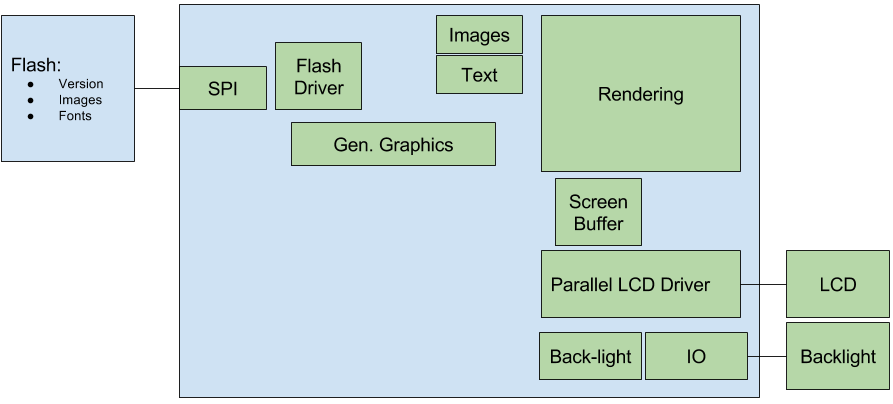
This is the type of diagram that I most often draw when designing a new system, and I find it immensely helpful. Elecia provides some good things to focus on when constructing it.
You should focus on separating protocol from the peripheral at this stage. You should also see by the connections made, which resources are shared more than others.
Hierarchy of Control

The hierarchy of control should be constructed by starting at a high level and then working your way down from higher-level concepts to more low-level implementation details. This also exposes the sharing of protocols and interfaces in your design.
Layered View
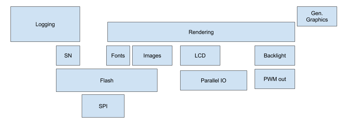
When constructing a layered view of your system, you can use the size of the block to show how much time you estimate it will take. Also, opposite from the hierarchy diagram, you want to build this from the lowest level, going up. As you build the layer, you should have any higher level blocks overlap with any lower level blocks that they use. This makes pieces of code that touch many others larger, and thus perceived as more difficult, since the more dependencies code has the more complex it usually becomes.
Creating an Architecture from the Diagrams
These diagrams can be very helpful, and should be reviewed and rewritten constantly. When reviewing it try to think about what could change. What can be grouped together, e.g. 2 components that only talk with one another, could be 1 component. Similarly, would it make more sense to split separate tasks up. This is an important part of the design process where you should clarify the API’s between separate components and (if you have people to delegate to) delegate the construction of those components. The point being, that these should now be very well-defined and separable units.
Elecia, further elucidated on some very handy practices that can be employed to allow for good debugging and design of your code.
Most of her drivers attempt to use the standard linux driver interface of
(open, close, read, write, ioctl). Having a standard interface can
help you swap in separate drivers very easily or simply think about different
components with a more standard approach. This hiding of specifics of the actual
implementation by a standardized interface is referred to as an adapter and is
always very handy in forming good abstraction.
Logging is used a design example and a few points are expounded upon, while
giving a great design for a very useful part of any embedded system. She
highlights the need for levels, a global on/off, versions, and a logging output
that consists of the system, level, message, and an optional number, to avoid
the need for costly printfs. A couple of good C design points are discussed,
such as the use of singletons: a once constructed item, where all subsequent
calls of instantiation simply return the first created object.
MVC frameworks are then discussed in terms of embedded systems and particularly as a means of testing them. A human readable file, a csv for example can be used to generate input to algorithms which then generate output files. These output files can be checked against over and over to perform useful regression tests. Also, when you get to test on your local computer you often avoid a lot Mjjkjof painful embedded debugging.
One last useful suggestion is to setup a style guideline. Elecia recommended Google’s C/C++ Style Guide.
Chapter 3: Making your Code Work
Chapter 3 was all about understanding parts, and being able to see inside (debug) things when they weren’t working. So, this chapter has a couple of big points: reading datasheets, understanding your processor, reading a schematic, collecting a good set of debugging tools, and testing your system. On top of that, Elecia elucidates the general steps of a project.
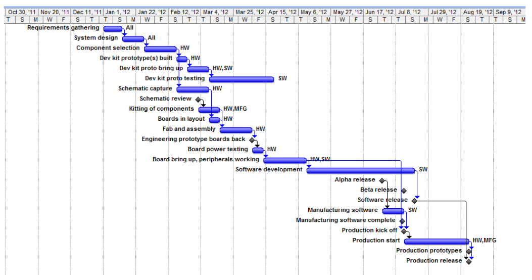
Most projects start with hardware selection, followed by board layout. This soon progresses into hardware tests to verify that all of the connections are properly made. Then there is the long cycle of software development work. The Gantt chart below elucidates the flow of most embedded projects.
Reading a Datasheet
Elecia lists all of the different parts of a datasheet along with helpful insights into what information to watch out for, these include the introductory description, the pin descriptions & layout, the schematics, any sample code, the performance characterization, and most importantly the application information / theory of operation. She also makes a note to look for any errata that the distributor may put out to fix previous documentation or device issues. Evaluating this list of fields will help determine if a certain peripheral can be used and if so, how easy it will be to implement.
Understanding a Processor & Reading a Schematic
A processor is the brain of any embedded system, as such, understanding a processor can make the difference between a working and a broken project. Elecia recommends using the user manual, getting started documentation, forums, and datasheet to really get a solid understanding of your processor. Understanding the schematic of your board isn’t too complicated and boils down to assigning meaning to the most connected pieces on the schematic, which tend to be the most important.
Debugging
A good hardware debugging toolbox is comprised of:
- Needle nose pliers
- Tweezers
- Box Cutters
- DMM (remember only test for resistance when the device is turned off)
- Electric tape
- Sharpie
- Screwdrivers
- Flashlight
- Magnifying glass
- Safety glasses
- Cable ties
Other extremely useful tools are oscilloscopes and logic analyzers. Elecia spends some time discussing how to use them, and their parts; including the time scale, voltage scale, and zero-offset.
Testing
In this section, Elecia really exposes her wealth of experience with work on embedded projects. She notes 3 main types of tests: POST, unit tests, and bring up tests. POST tests stands for Power On Self Test, and should be run every time on boot to check that everything is connected properly. Unit tests should atleast be run at every release, and it is a good idea to try to leave them in production for easy debugging. The bring up tests should check specific subsystems and are usually one-off / throwaway tests. Elecia uses Flash as a good example for tests, including the reading, byte access, and block access of flash in her tests.
Having a command and response debugger can also be very helpful for selectively running separate functions. Here’s a code-snippet of the structure that Elecia uses in her debugger.
typedef void(*functionPointerType)(void);
struct commandStruct {
    char const *name;
    functionPointerType execute;
    char const *help;
};
const struct commandStruct commands[] = {
    {"ver", &CmdVersion, "Display firmware version"},
    {"flashTest", &CmdFlashTest, "ReRuns the flash unit test, printing out the number of errors"},
    {"blinkLed", &CmdBlinkLed, "Sets the LED to blink at a desired rate (parameter: frequency (Hz))"},
    {"",0,""} //End of table indicator. MUST BE LAST!!!
};
Elecia further recommends the use of an eror handling library with a
well-defined errors file to know which codes mean what. This library should
usually set a global error flag, and have an interface comprised of set,
get, print, and clear functions.
Chapter 4: I/O & Timers
This chapter starts off by diving right into the use of registers, how that extends to memory-mapped IO, and the consequent need for a proficiency in binary operations. We then delve into how I/O has different types and directions and how it all depends on the vendor. Elecia recommends having a board-specific header file which can be selectively included like this:
// ioMapping.h
#if COMPILING_FOR_V1
#include “ioMapping_v1.h”
#elif COMPILING_FOR_V2
#include “ioMapping_v2.h”
#else
#error “No IO map selected for the board. What is your target?”
#endif /* COMPILING_FOR_*/
Then she describes how different response times feel:
| Sluggish | Good | Snappy |
|---|---|---|
| 250 ms | 100 ms | 50 ms |
We then get into the good stuff, with Elecia describing the differences between interrupts and polling. She then implements a neat button debouncer using a timer and a filter.
Then the design patterns get into the mix. Elecia compares the Facade pattern with Dependency Injection. Facade reduces complexity by simplifying the lower-level interface. With the LED example that she gives, this is done by abstracting away the IO interface into the LED code. It makes the LED code rely on the IO though. Dependency Injection aims to increase flexibility; as an example you’d pass in a IO handler to the LED code, so you could do anything when turning it on. This is handy when working with different boards, or even for testing, for example you could write to a file instead of turning an IO pin on. Facade pattern takes up more space, but Dependency Injection can add to the run time, due to the use of function pointers.
Then we take a good look at timers, evaluating their various registers which can include: total_time, compare, action, clock, prescale, control, and interrupt. Here’s a neat algorithm to settle on a pre-scalar & compare value:
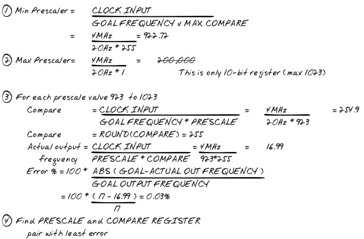
Note that the main issues to solve here are the limited width of the register and the fact that we’re working with integers instead of floats. Elecia then makes a lovely transition from the discussion of timers to describing PWMs as 2 timers.
Chapter 5: Task Management
Elecia prefaces this chapter by stating that chapter 2 was the what/why of design and this is the how.
OS
We start off fast by diving right into operating systems, and distinguishing between tasks, threads, and processes. We then get into scheduling and communication between threads (Elecia uses globals). We establish separation of critical sections via mutexes, which can, at their very simplest, disable interrupts. She has a view on semaphores, that I haven’t seen before, she refers to them as such:
Operating systems have heavier weight mutexes called semaphores that can handle situations where a thread or process can be preempted (for- cibly changed by the scheduler).
I’ve only ever dealt with semaphores that are used as an alternative to mutexes and are usually better for signaling between producers and consumers, but don’t take my word for it. Make sure that when you’re in your ISR that you finish quickly. Elecia also gets into why we need priority inversion and how it works.
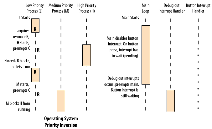
FSM
Elecia then gets into Finite State Machines which, put very simply allow a
change of behavior when the state changes. It usually is implemented with a
switch statement, you can separate this next_state utility into a function.
Alternatively, it can be event-centric. These usually need 5 functions to use
for each state: enter, exit, go, stop, periodic_housekeeping; go and
stop are implementation specific event handlers, there could be many more of
these event handlers, but her example is a stoplight, so these handlers make
sense. Alternatively you can use a table to keep track of your FSM, in it you
have a pointer to what do to do in a go, stop, and timeout situation as
well as a light that’s associated with that state. Then there are global
handlers that call the necessary functions when they are required.
Interrupts
Once an interrupt occurs a very particular set of steps takes place:
- IRQ
- Save Context
- Go to the IVT (Interrupt Vector Table) for the Callback
- Execute the Callback
- Restore the Context (Elecia, didn’t mention this, as it’s often take care of by the compiler, as is #2
She quickly makes a distinction between a normal interrupt and an exception. The use of separate set & clear registers is shown to prevent interrupt issues since you don’t have to read any register to clear / set a bit. There’s also a quick reminder about setting global interrupts. There’s a quick discussion about interrupt priority and nested interrupts. Elecia recommends staying away from nested interrupts, and I must say that I agree with her. Interrupt latency is taken into consideration, as an overall metric of the processor.
Functions called from the IRQ must be reentrant, which means that they can be run multiple times without being complete; this makes most functions that use global state non-reentrant. There’s a good example of where the vector table is located in the LPC17xx:
__attribute__ ((section(".isr_vector")))
void (*const g_pfnVectors[])(void)//* put here to fix markdown issue
= {
    // Core Level - CM3
    &_vStackTop,
    // The initial stack pointer
    ResetISR,
    // The reset handler
    NMI_Handler, // The NMI handler
    ...
    TIMER2_IRQHandler, // 19, 0x4c - TIMER2
    TIMER3_IRQHandler, // 20, 0x50 - TIMER3
    UART0_IRQHandler, // 21, 0x54 - UART0
    ...
}
There’s a useful hint about saving the interrupt status when you disable it, so that when you re-enable you don’t accidentally turn it on, when they were already off. The concept of a system tick is explained and the reader is made aware of it’s necessity in any scheduler. A small pseudo-scheduler is explained that uses a pub/sub model. Then the concept of a watchdog is explained, noting its ability to greatly increase the robustness of a system.
Chapter 6: Peripherals
This chapter discusses how peripherals fit into embedded systems, compares and contrasts some, looks into communication methods between processors and peripherals, and then takes a gander at the software that makes them all work together.
Types of Peripherals
Elecia very briefly discusses memory before getting into buttons and key matrices. A cheap matrix can be made using row/col scanning to get an M x N matrix using M + N lines. Row/col scanning involves turning rows on in sequence and seeing which columns are on at each point. An expensive one uses Charlieplexing to get `N^2 - N matrix using N lines & N diodes. Elecia doesn’t explain it, but offers this link to use to figure it out. It’s pretty neat, and uses the high-impedance state of output pins to do it’s work: here’s a somewhat useful picture:
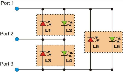
We then get into sensors and some fun talks about DSP and FCC radiation
regulations. Actuators, and motors of all varying types (brushed, stepper,
brushless) are all discussed. This broaches the topic of linear and rotary
position encoders. Rotary ones tell you which of ~8 positions it is in, linear
will increment every time it rotates a certain amount. Some timer/counters can
increment this value for you. The topic of motors always lends itself nicely to
PID control, which at its roots is merely the use of feedback in a system
based on the error (difference between current point and target point). She uses
a methodology where you set the P, then I, then D, whereas I was taught to
set P, then D, then I only if you must since I can cause a bunch of
problems. A more intricate solution is the Ziegler-Nichols
method. There’s a
great explanation of implementing PID
here.
We then get into displays, like 7-segment LEDs and start discussing graphic assets and glyphs. Elecia drops off into a whole tangent about glyph layouts. There’s a neat design here:
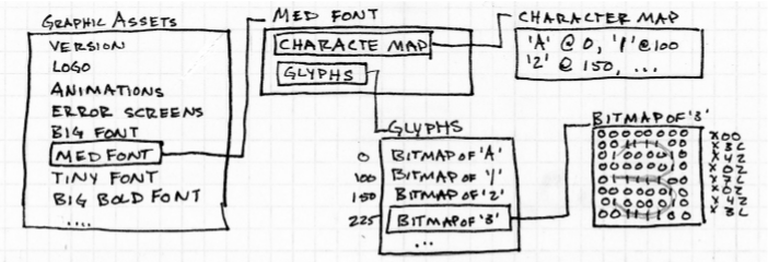
Then she uses that to talk about RLE (run length encoding) to encode bitmaps. She also discusses anti-aliasing to soften edges of graphics.
Communication Protocols
OSI layers are brought to the forefront of the topic, these are a separation of responsibilities in a communication stack and are comprised of:
- Physical - bit transfer
- Data - byte transfer
- Network - variable length packet transfer
- Transport - move blocks (could be larger than max packet)
- Session - manage connection between local & remote
- Presentation - provide structure, maybe encryption
- Application - UI
We’re mostly concerned with the data layer. Elecia discusses ethernet and wifi briefly, then discusses serial, SPI, I2C. I also learned that TTL is (0~3V) while RS-232 (+/- 12V). Here’s a little handy table that I put together from the rough approximations that Elecia gave:
| Serial | SPI | I2C | 1-Wire | USB | |
|---|---|---|---|---|---|
| Length | 15m | < 1m | + 3m | 10m | 5m |
| Speed | 2400 - 115200 | 100 MHz (clk dependent) | 10kbps, 100k, 400k, 1M | 100k | 400M |
| # wires (w/o gnd) | 2 [RX, TX] (agreed clk) | 4 [MOSI, MISO, CLK, CS] | 2 [SCL, SDA] (128 possible devices) | 1 (agreed clk) | 3 (Really Complicated) |
She then mentions parallel buses, as another way of moving bits even faster.
Putting it Together
When we are gathering all of this data, we need somewhere to put it, circular buffers are a great place to put it, as my friend Chris knows all too well. You can do a couple of tricks when working with circular buffers, one is to add anoter pointer to the structure that keeps track of where it is now free to add more elements. So, you end up with a couple of different sections of your buffer, free to write (b/t write & free ptrs.), free to read (b/t read & write ptrs.), and currently being read (b/t free & read ptrs.)
There are also, sometimes hardware implemented datastructrures in which you can store your data, the most common of which is a FIFO. DMA’s don’t necessarily store your data, but allow you to send and receive large amounts of data out of band from your typical processing, which can signicantly improve runtime, while adding some complexity. Elecia then shows off some nice math to analyze how much faster DMA is than bit-banging.
To make our communication robust it’s often a good idea to version our code and checksum our packets, CRC is a good checksum to use.
We then discuss design patterns briefly. The different patterns are flyweight and factory. Flyweight pattern apparently refers to a large collection of objects, such as a glyphset. A factory pattern is about subclassing things. Here’s an example that she gave:
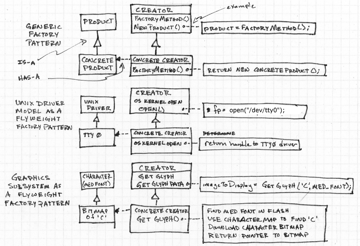
I’m not really sure why she added this here, it seemed very superfluous.
Chapter 7: Updating Code
This chapter deals with the whole issue of deploying code, after the hardware has left the building. There are a lot of concerns to keep in mind when performing these sorts of updates, not least of which are the storage mechanism, communication protocol, rom programming, scratch RAM, and running RAM.
Bootloaders
You can update code like this with the use of a bootloader, there are a couple of different types of bootloaders.
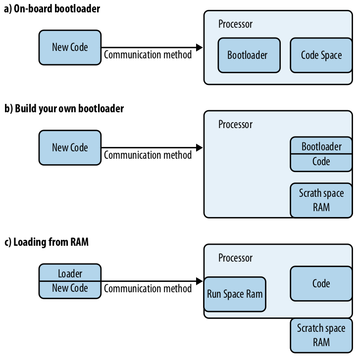
- On-Board Bootloader: On load put code directly on system, this bootloader is usually completely separate from your code, offering great simplicity, but not much flexibility.
- Build Your Own Bootloader: This bootloader is mixed with your other code, and makes use of RAM to store downloaded code temporarily, it is then verified with a CRC.
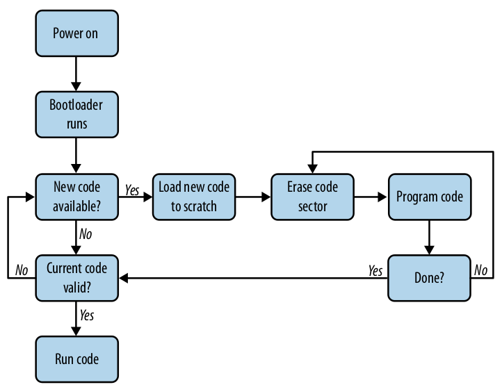
- Modify the Bootloader: Load a bootloader, that writes itself into where the old one used to be.
- Brick Loader: This can brick the device in between erasing the flash and having the new code fully loaded onto the system. Keeping this window small is a design constraint. This runs code from ram, which some processors disallow. It then copies the new code to scratch, erases the old code, and programs the new code.
Linker Scripts
The chapter then uses bootloaders to launch into linker scripts, and the general process of linking. The linker forms an executable which has these 3 segments:
bss: uninitialized global in RAMdata: initialized globals in ram (may have heap/stack, andbssas subsegment)text: code & constants, ROM/RAMvector: interrupt vector table
When you’re modifying the linker script start from the initial .ld script and
work off of it. You can use the map file to confirm your changes. Elecia uses
the linker scripts to help create this bootloader. She gets the functionality as
seen in this diagram.
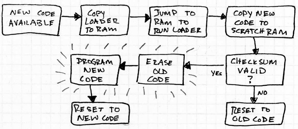
I wasn’t sure about why she needs to copy the loader from RAM and not just execute it in ROM, but since we’re overwriting ROM, we don’t want to accidentally overwrite what we’re doing right now.
The loader can reside on the system, but that would require an ability to leapfrog to newer versions, or you could get it from the same location that you get the new code.
This definitely raises some security concerns, some possible countermeasures involve non-readable on-chip ROM.
Chapter 8: Optimizing Code
We should forget about small efficiencies, say about 97% of the time: premature optimization is the root of all evil. - Donald Knuth
When we try to optimize something, we must first ask ourselves what we’re optimizing for, some of the things to consider are development time, code space, amount of RAM used, and # of cycles used.
Code Space
When optimizing for code space viewing the map file can be extremely helpful.
The .rodata section holds read only data, an interesting fact is that
#defines take up space, but can’t be seen very well in the map file, while
consts take up the same amount of space but can be seen.
Always try the easy way first, and try applying the -Os (letter, not #). When making optimizations, it is a good idea to keep track of changes made in a table not unlike this:
| Action taken | text |
data |
Total | Total (hex) | Freed | Total Freed (since start) |
Libraries can be a large source of bloat, getting rid of the need of them can
significantly reduce code size. Macros and functions have an interesting
tradeoff, macros take up more code space, while functions add an entry on the
stack. Another thing you can do is #define logging away when it is not being
used, e.g. production.
RAM
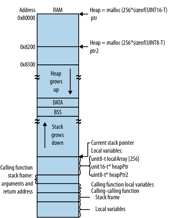
First and foremost try to get rid of dynamic memory allocation, which can lead to wasted RAM, loss of processor cycles, and fragmentation. You can do this with the use of globals, which while frowned upon, can be seen as quite beneficial to the alternative on an embedded system. You can use a ping-pong buffer when getting interrupt data, which flips between 2 buffers, changing the pointer once the data has been written successfully.
When passing in function pointers, try to stick to using n-bit parameters for an
n-bit processor and pointers for structs. You can learn about the assembly by
reading the list (.lst) file. Recursive functions kill the stack so don’t do
them, unless it’s tail recursive (then the compiler can optimize it away).
One neat trick is to overlay different memory resources that aren’t used at the same time onto the same area of physical memory. You can do this by creating a union of several structures that has an owner, creating a singleton to manage the buffer, or modifying the linker script (which makes everything seem completely normal, adding no interdependencies, but adds a hidden constraint on your code).
Speed
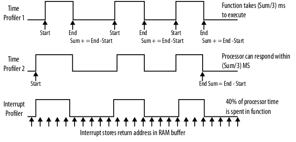
You can profile the speed of your code by raising / lowering I/O pins when you enter / exit a function and viewing the output with and oscilloscope. You can also time functions by counting cycles, and running things a couple of times to get a good average, then logging the result. You can also do that with functions that are much shorter, by allowing them to run multiple times in between taking time. You can also make a sampling-based profiler which samples at a time that is aperiodic with any other interrupts you have and logs the return address of where it was, this allows you to see what interrupts you’re in / what pieces of code you most often find yourself.
Miscellaneous Optimizations
- Possibly try moving code to faster RAM
- Use native processor data size
- Flatten function calls
- Use pointer arithmetic as opposed to arrays and indices
- Unroll loops
- Use lookup tables
Elecia added a pretty clever analogy to explain to non-technical people the reason behind optimizations.
Chapter 9: Embedded Math
There are a lot of useful mathematics involved when working with integers on
embedded systems. Elecia highlights this when she defines precision as noise.
She gives us a good hint to try using bit operators whenever we can to avoid
performing costly divides and %s.
We get into filters pretty quickly, and evaluate the difference between a block and rolling average. The block only updates on a set period, but allows for many less divide operations.
Generally try to apply Horner’s Scheme which means diminishing the amount of costly operations that you have to do when performing arithmetic. Using the taylor series is immensely useful for approximating real world applications. Often when doing the necessary divides you can alternatively multiply and shift, which is much more efficient. You can also scale the input from (-1, +1) to something like (-1024, +1024), which reduces noisy precision and allows you to keep using integers. Make sure you watch out for overflows. When using Taylor series you can often use a lookup table. You can combine that with linear interpolation, so that you can have more points cover the more tricky parts of your function. It also allows you to predict past your table.
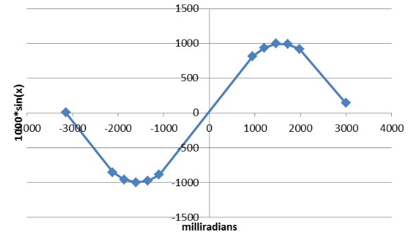
You can also fake floating point by using fixed point numbers with binary scaling.
Chapter 10: Optimizing for Power
When trying to reduce power turn off everything that you’re not using. Realize that this sacrifices time it takes to get them up and running again. When configuring IO pins try to set them as pulled-down inputs, if that’s not possible pulled-up inputs, and if that’s not possible a low output. You can also slow your clock down. Also, you can set your processor into a sleep state:
- slow
- idle / sleep
- deep sleep
- power down
- power off
Note, that the further down you go, the less power you use, but the longer it takes to get back to a usable state. Don’t forget to disable your watchdog when sleeping, or pet it every so often. You can also chain smaller processors to larger ones, to use less power and only wake them when entirely necessary.
Closing Takeaways for my Future Work
I thought this book had a lot of really useful advice, but at the same time it ddn’t seem very cohesive. I think focusing on a project might help with that issue or simply having more of a linear progression between ideas.
Ideas
- Map file parser to profile code size
- Write a bootloader
List of Possibly useful references that Elecia mentioned
- Design Patterns: Elements of Reusable Object-oriented Software
- Head First Design Patterns
- Object Oriented Programming in ANSI-C I think?
- Make: Electronics
- Designing Embedded Hardware
- A Guide to Debouncing, a great article on the causes of bounce and the solutions of it
- Operating Systems Design and Implementation
- Programming the 6502, or other processors from around 1980 give good references
- The Scientist and Engineer’s Guide to Digital Signal Processing
- Signals & Systems
- The Art of Control Engineering
- Smart Card Handbook, a good book about security
- James Lynch’s Serial Communications Tutorial for the AT91SAM7, a handy tutorial on setting up open-source tools
- AVR035: Efficient C Coding for AVR
- Hacker’s Delight
- Art of Computer Programming, specifically Vol. 2 for the great algorithms
- Art of Electronics
- Numerical Recipes: The Art of Scientific Computing
- There Are No Electrons: Electronics for Earthlings
- MSP430 Coding Techniques App Report

